
David Baker (sirbakes@umich.edu)
Illi Eisner (ieisner@umich.edu)
Dan Zhang (danz@umich.edu)
|
Project BARBIE JEEP David Baker (sirbakes@umich.edu) Illi Eisner (ieisner@umich.edu) Dan Zhang (danz@umich.edu) |
|
Table of Contents
Introduction
High Level Design
Task Distribution
Hardware Design
Software Design
Results of the Design
Conclusions
Media
References
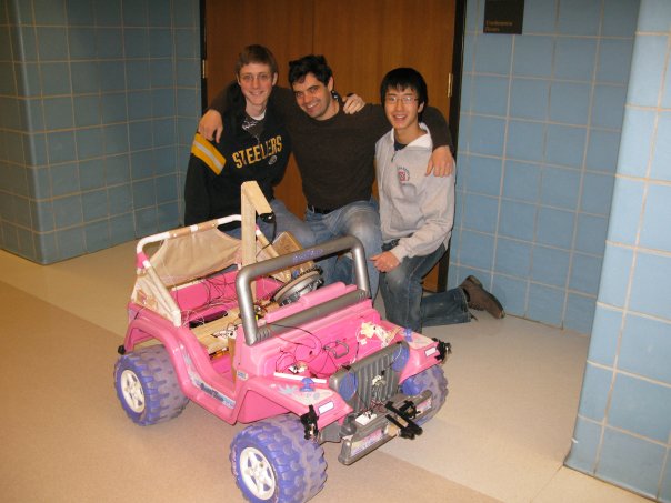
Project BARBIE JEEP was inspired by the DARPA Grand Challenge, in which universities design autonomous robots based on production vehicles, which then race across the desert using GPS and various types of sensors. Our original project proposal was intended to be a small scale version that would be achievable given our time span. Due to time constraints, unfamiliarity with the MPC555, and other problems, the project had to be scaled further back into a simple robot that would navigate hallways with sensors. We were able to achieve this goal while solving many problems that previous groups had with the MPC555.

For the EECS373 final project, team BARBIE JEEP designed and implemented a fully autonomous robot using the Fischer Price Power Wheels platform. Due to the mobile nature of the platform, we chose the MPC555 over the traditional MPC823, which offers a smaller form factor, easier power regulation, and lower power consumption. To allow the robot to examine its surroundings, 8 Sharp IR sensors and 1 sonic sensor were mounted at various points on the vehicle. A drill motor was used to turn the steering wheel via a chain and sprocket design. To control the high-current drill motor as well as the drive motors, H-bridges were designed using 30-amp relays. A simple robotics program was programmed onto the MPC555 flash memory (bootable from flash), which would use the inputs provided by the sensors to control the two H-bridges.
We were able to obtain a used Barbie Crusin' Tunes Power Wheels vehicle from Craigslist for $40
| Task | David | Illi | Dan |  |
| Steering | 50% | 50% | 0% | |
| H-bridge | 50% | 50% | 0% | |
| Voltage Regulation/Analog | 75% | 25% | 0% | |
| Wiring | 25% | 75% | 0% | |
| Sensors | 33% | 33% | 33% | |
| Flash Programming | 0% | 0% | 100% | |
| Interrupts | 0% | 0% | 100% | |
| I/O (PWM, TPU, etc) | 10% | 10% | 80% | |
| Robotics Algorithm | 25% | 0% | 75% | |
| Report | 33% | 33% | 33% | |
| THE BEST THE BEST | 0% | 0% | 100% | |
| Total | 33% | 33% | 33% |
We used 2 DC motors to drive the rear wheels of the car and one for the steering. The steering apparatus was constructed from a bike chain and a pair of bike gears one of which was attached to the steering wheel and the other was created to act as a drill bit, and was powered by a modified electric drill. We used mechanical relays to create h-bridges in order to switch the polarity to the drive, and steering motors. In order to switch the relays, we needed to use the amplifier circuits from lab 7 because the general purpose I/O pins that we used for the control signals to the H-bridges could not provide a large enough voltage differential to switch on the relays.
We used both IR and sonic distance sensors to detect things in the way of the jeep. We also used an IR sensor to detect the current position of the steering wheel. The TPU_accumulator function was used to count the amount of high time of the pulse signal from the sonic sensor. We had 4 batteries powering the different parts of the jeep, a 12v car battery for the drive, a 9.6 v drill battery for the steering, and two 7.2 v battery packs for the 555 board and the sensors. We used a simple power regulator circuit to apply 5v to the sensors from the 7.2 v battery.
The steering proved to be one of the more challenging aspects to our product because the chain needed to be taught and the two gears had to be on the same plane or the chain would slip off. The steering wheel of the jeep was poorly made and it could tilt from side to side changing the plane of the wheel. We tried to fix this by pulling the wheel to one side and making the chain tight in order to keep the wheel from moving when it wasn’t supposed to. Because of the large amount of torque that we needed to turn the steering wheel of the jeep, over steering sometimes caused the plastic to buckle slightly and the chain would pop off. In order to help prevent over steering we pulsed the motor controlling the steering and used a sensor to detect the current position of the steering wheel, we would turn off the motor once the wheel reached its final position for the turn.
Hardware Design - H-BRIDGE + AMPLIFIER
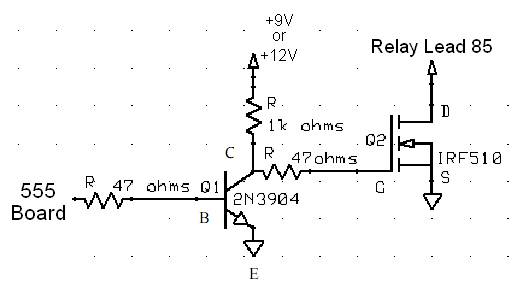
The design of the Barbie Jeep stipulated that steering and motor control would be controlled through the MPC555 general purpose I/O pins. This, however, posed a challenge as ordinary transistor control circuits would not work (i.e. they would be fried) with the high-current batteries required by the Barbie Jeep drive and steering motors. We therefore implemented a two-stage solution that no only allowed the 555 board to control and even pulse-width modulate the motors, but integrated a custom H-bridge that allowed for directional functionality.
A combination of transistor control circuits and automotive relays allowed us to bright the gap between the 5V 555 board and 12V, 30A drive motors and 9V, 12A steering motor. The transistor circuit, shown below, interfaces the 555 board to the automotive relay. Since the transistors drew little current from the batteries and the n-mos IRF510 transistor closed the relay circuit with ground instead of VCC, the solution averted conditions where turning on the Jeep meant starting a fire. A +5V input from the 555 board causes the transistor circuit to connect relay lead 85 to ground. This, in turn, closes the switching circuit between relay leads 30 and 87 (see 5-pin mini relay diagram) which easily handle the high current drawn by the drive and steering motors.
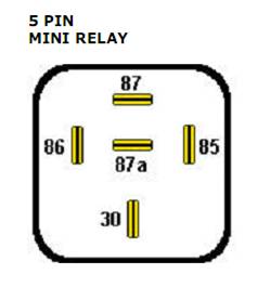 The automotive relay, shown below, is a standard 5-pin, 30 amp plug-in unit. The pin connections were as follows:
30 – Motor battery source
87 – Motor VCC input
85 – Transistor circuit output
86 – Motor battery source
87a – Not Connected
Using a series of 5 pin relays a custom h-bridge was constructed that allows the 555 board to control the direction in which the steering and drive motors operate. The following diagram depicts this h-bridge circuit.

It is critical that all grounds between the 555 board, transistor circuits, batteries and relays are common. Otherwise, mysterious physical and often smoky anomalies take place. The h-bridge operates by triggering a combination of transistor circuits to close the circuits in particular relays thereby reversing or maintaining the polarity at the motor leads. The combinations are as follows - take caution, as any other state not listed may result in a short circuit.
“Forward” Operation
Trigger Transistor Circuit A
Trigger Transistor Circuit B
“Reverse” Operation
Trigger Transistor Circuit C
Trigger Transistor Circuit D
“Idle” Operation
No Transistor Circuits are Triggered
We implemented a simple path finding algorithm in software. It used the information supplied to the processor by the various IR and sonic sensors to decide which position the steering wheel should be in (right, center, or left). And whether it should go in forward or reverse. The algorithm was a three state finite state machine, where the first state was when it did not detect anything on either side and nothing in front of it, this state set the steering wheel to the center position and it moved forward. It would enter the ‘turn’ state when ever it detected something in front of it but the object was not so close that it was about to run into it. In this state it would choose to turn left or right based on the results that the right and left sensors returned. The final state was the reverse state it would enter this state if it ever got too closes to and object, in this state it would continue to back up until it detected something on one of the back sensors.
In the most part our design worked the way we expected it. Our original design called for some sort of method to keep the vehicle’s current position and final destination to allow the jeep to navigate to different destinations. GPS was dropped from the design at the start due to the fact that we could not get a signal inside the EECS building. We were instead going to use a castor wheel attached to the back of the jeep to record distance traveled and direction facing information to use a mapping algorithm. We had to drop this from the design however, because we did not have enough time.
Originally we hoped to be able to run the jeep at full speed, but the range on the sensors was not long enough to provide the jeep enough time to react to different obstacles when traveling at this speed so we had to pulse the motors to make the jeep travel at a more manageable speed.
In the end Barbie Jeep worked pretty well. However, there were a few blind spots, and the IR sensors don’t work well with rounded edges or glass. The majority of our time was spent on the steering, h-bridges, and flash programming.
We spent a lot of time trying to get flash to work so we could use interrupts and use the sonic sensors. In the end we were able to get flash to work. The guide to using flash should help prevent groups in the future from suffering from further indignities.
We believe that it was possible to implement our original idea at a reduced speed with the components we had. With more time we could have gotten the positioning system of the jeep to work.
Knowing what we do now, we would have made more permanent connections between relays and the analog circuits to prevent errors that were caused by bad connections between wire and other components such as the relays, batteries and analog circuits. We also now realize that the MPC555 board can be really useful in many applications. However, getting used to a new board in the three weeks can be stressful, especially when things are not working as you would expect them too.
Also, choosing to use a larger vehicle such as the Barbie Jeep made some aspects simpler, such as finding place to transport the board and batteries. However, the larger size can make the mechanical aspects of the project more challenging - the steering mechanism was particularly challenging and caused most of our problems.
Fully formatted final video:
Raw videos:
http://www.axman.com/?q=node/171
http://www.eecs.umich.edu/courses/eecs373/Labs/Web/W08/Rob/index.html
http://www.eecs.umich.edu/courses/eecs373/Labs/Web/W07/Cliffhanger/index.htm
Dummy's Guide to Flash <- Use this to learn Flash Programming!